


A housing can look securely installed and still leave a bearing working under unwanted load. A paint ridge behind the flange, a damaged locating shoulder, or a shaft pulled sideways during tightening may not be obvious until vibration returns after reassembly. For after-sales maintenance personnel working with an SKF FNL513A Cast flanged housing, the useful question is not simply “Are the bolts tight?” It is “Does the housing sit correctly, and does the shaft remain aligned when the bolts are tightened?”
This guide focuses on those checks. Use the applicable SKF housing instructions, bearing installation guidance, and machine drawings for dimensions, permissible deviations, fastening requirements, and lubrication details. Do not substitute a generic torque value or alignment tolerance for the requirements of the actual assembly.
Before removing the housing, preserve the evidence
When a machine returns with noise or rising temperature after a bearing replacement, dismantling immediately can erase valuable clues. If operating conditions permit safe assessment, record vibration, temperature, speed, and load before shutdown. Note whether the symptom began immediately after installation or developed gradually.
Then isolate and lock out the machine, release stored energy, and support the shaft and connected components as required. Never loosen a housing that is carrying an unsupported shaft or external load.
Photograph the flange, bolt positions, locating features, and any shims before disturbing them. Mark component orientation where appropriate. Unequal gaps, fretting around one mounting area, or a witness mark concentrated on one side can help explain why a replacement bearing has not solved the problem.
- Confirm the housing designation and the installed bearing designation separately.
- Check the arrangement drawing for locating and non-locating bearing positions.
- Identify the intended alignment datum: a machined register, shaft centerline, mating flange, or another specified reference.
- Review previous maintenance records for recurring bolt loosening, abnormal heat, or repeated bearing changes.
A self-aligning bearing may accommodate some angular misalignment within its permitted limits, but it does not make a distorted mounting surface acceptable. Nor should it be used to compensate for an incorrectly positioned housing.
Reading the mounting face: cleanliness is only the starting point
Clean both the housing mounting face and its support surface using methods suitable for the materials and surrounding seals. Remove loose dirt, old sealant, corrosion debris, and excess coating without changing the geometry of the machined surfaces. Keep contamination out of the bearing cavity.
Pay particular attention to bolt holes and locating features. A raised edge around a hole can hold the flange away from the support even when the rest of the surface looks clean. Burrs, embedded particles, and thick paint can create the same effect.
Minor raised burrs may be removed using an approved maintenance method. Broad unevenness, cracks, damaged registers, or significant corrosion require assessment rather than improvised grinding. Do not hand-grind the entire flange to make it “sit better”; that can alter the relationship between the mounting face and bearing seat.
Use a suitable precision straightedge and feeler gauges for accessible support surfaces, or a more appropriate metrology method where the geometry demands it. Check in several directions and record the readings against the machine’s specified flatness requirements. A single straightedge position can miss a local high spot.
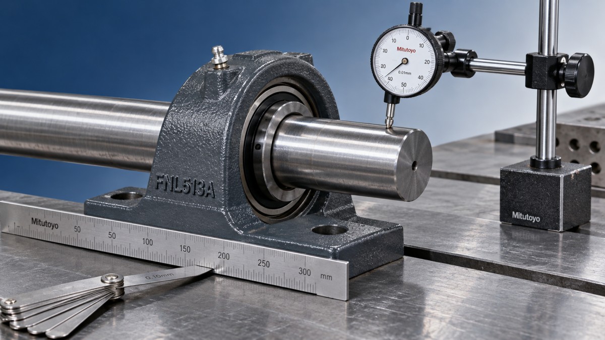
Where permitted, a controlled contact-pattern check can help identify high spots. Apply any marking medium sparingly and remove it completely afterward. The objective is to understand contact at the intended mounting areas, not to create an apparently perfect print through excessive force.
Establish the housing position without forcing the shaft
With the surfaces prepared, check any specified locating diameter, shoulder, pilot, or dowel arrangement. These features may determine housing position more accurately than the bolt holes. Confirm their condition and fit before using fasteners to secure the assembly.
The housing should engage its locating features according to the documented installation method. Resistance is a reason to investigate, not to use mounting bolts as a press. Tightening against an obstructed register can damage the locating surface or load the housing unevenly.
Bring the housing into position while supporting the shaft appropriately. Fit the specified fasteners and washers, then secure them lightly enough to retain the assembly without masking a seating problem. Check accessible interface areas for unexpected gaps. Avoid treating a gap at a casting relief or another non-contact feature as a defect; compare what you see with the housing geometry.
If shimming is permitted by the machine design, use the specified materials and arrangement. Random stacks of thin shims or partial support beneath the flange can introduce another source of distortion. Where correction requires machining or structural repair, follow an approved repair plan.
Checking SKF FNL513A Cast flanged housing alignment during tightening
Alignment is not one measurement taken before the bolts are tightened. It is a comparison between the lightly secured condition and the fully secured condition.
Select the method to suit the assembly. Dial indicators may be appropriate for shaft position, runout, or movement relative to a fixed datum. A laser alignment system may be useful for coupled shafts, while dimensional checks may be needed to establish the housing position relative to a machined frame. Coupling alignment alone does not prove that the housing mounting face is seated correctly.
- Establish a baseline. Record shaft position and relevant alignment readings with the housing lightly secured and the shaft correctly supported.
- Tighten progressively. Follow the prescribed sequence and torque procedure. Use calibrated tools and the specified fastener lubrication condition.
- Watch for movement. Recheck readings as clamping load increases. A repeatable shift associated with one fastener suggests a seating or support issue worth investigating.
- Verify the completed arrangement. Confirm final alignment, required axial freedom, and clearances against the equipment documentation.
Do not tighten by feel to eliminate a visible gap. Bolt torque is not a corrective tool for poor geometry. Also distinguish shaft runout from shaft misalignment: a bent shaft or an eccentric measuring surface can mislead an otherwise careful alignment check.
Keep replacement-bearing selection separate from housing correction
If inspection also identifies bearing damage, confirm the replacement from the complete bearing designation and arrangement requirements. Bore size alone is insufficient. Bearing type, fits, internal clearance or preload, cage, seals, and operating duty all matter.
Jinan Lanyu’s bearing import and export portfolio includes deep groove ball bearings, self-aligning ball bearings, and cylindrical roller bearings. For separate precision applications requiring angular-contact support, its product information also lists the NSK 30TAC62CSUHPN7C Angular Contact Ball Bearing, with nominal dimensions of 30 × 62 × 15 mm. That listing is not a compatibility recommendation for the FNL513A housing. Verify the manufacturer’s designation, bearing arrangement, and application requirements before ordering; supplier-listed options should not replace model-specific technical confirmation.
Return to service with a record, not just a tightened flange
Before restart, verify lubrication, seals, guards, fasteners, and any disturbed couplings. Where the machine design permits, check rotation using the approved safe method. Unexpected binding or resistance calls for investigation before powered operation.
Restart according to the equipment procedure and compare vibration, noise, and temperature with the available baseline under comparable conditions. Avoid declaring success from a brief unloaded run if the original problem occurred under working load.
Close the job with the support-surface findings, alignment readings before and after tightening, fastening procedure, and any corrective work. Those records make the next diagnosis faster. More importantly, they help separate installation faults from bearing damage—so the maintenance team is not replacing another bearing while leaving the original cause behind.
Navigation
Send Us A Message
consult

Jinan Lanyu Import & Export Co., Ltd. is a bearing manufacturing enterprise specializing in the import and export trade of bearings. Covering a total area of 50,000 square meters, the company boasts an annual production capacity exceeding 20 million sets and is dedicated to the manufacture of high-quality bearings.

First class quality service and professional after-sales team.
Get in Touch
*We respect your confidentiality and all information are protected.
