An Angular Contact Ball Bearing can appear flawless yet fail acceptance if dimensional accuracy or runout exceeds specified limits. Appearance alone cannot establish suitability.
For quality control and safety personnel, reliable inspection identifies assembly risks before bearings enter service. Acceptance requires agreed limits, suitable equipment, and traceable measurement results.
This guide explains how to verify precision and measure radial and axial runout under controlled conditions, with attention to applicable standards and inspection records.
Align each check with the required tolerance class and application demands. This supports defensible decisions and reduces the risk of vibration, overheating, and premature failure.
What Must Be Agreed Before Inspection Starts?
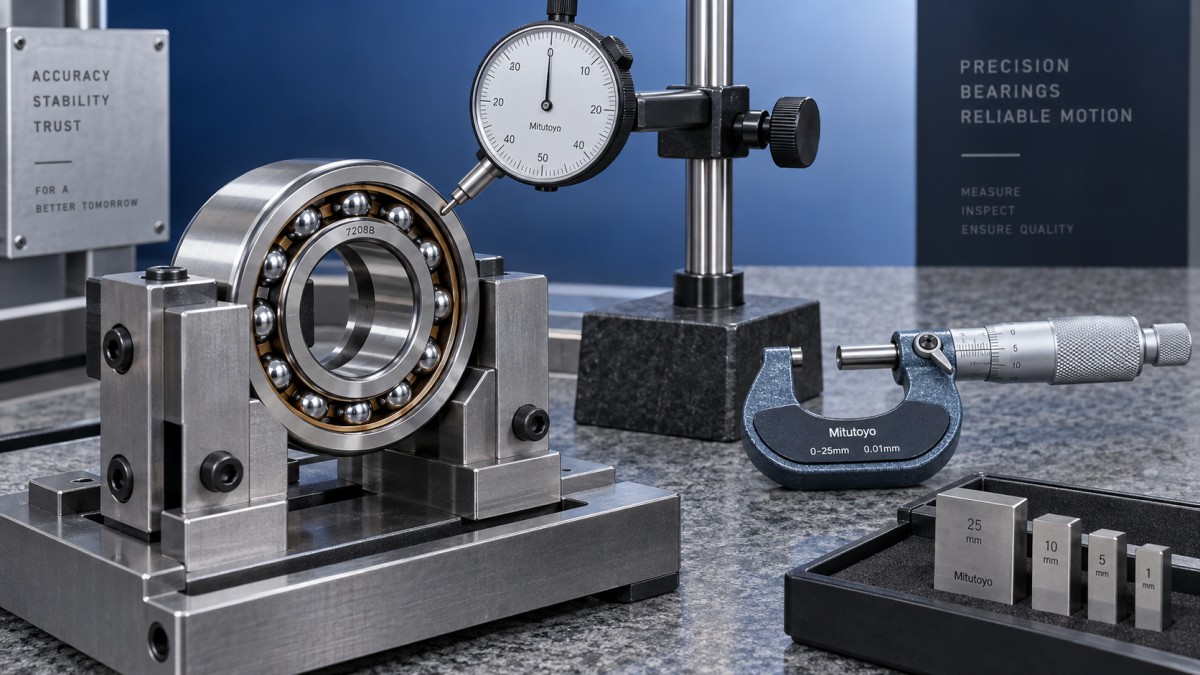
Start with the purchase specification and bearing designation. Confirm the manufacturer, size, contact angle, tolerance class, arrangement, and any requirements for matched bearing sets.
Acceptance limits must come from the approved drawing, purchase agreement, or applicable standard. A generic runout value cannot reliably qualify every angular contact bearing.
ISO 492 defines dimensional and geometrical tolerances for radial bearings within its scope. Use the specified edition and the tables applicable to your bearing.
ISO 1132-2 provides measurement and gauging principles. Manufacturer procedures may add instructions for seating loads, measuring positions, and matched sets that your inspection must follow.
Do not automatically equate ISO tolerance classes with ABEC designations. Confirm the governing standard and individual limits, particularly when suppliers use different classification systems.
A P5 or P4 designation does not define contact angle, preload, lubricant, or speed capability. Those characteristics require separate verification against the application specification.
For matched pairs, verify pairing marks, mounting orientation, and set identification. Individually acceptable bearings can still form an unsuitable assembly when pairing requirements are ignored.
Which Checks Establish Dimensional Precision?
Dimensional inspection confirms whether the bearing will fit its intended shaft and housing. Check bore diameter, outside diameter, and ring widths against the specified limits.
Use calibrated bore gauges, suitable comparators, and micrometers with adequate uncertainty. Instrument resolution alone does not demonstrate that a measurement can support an acceptance decision.
Measure diameters at the axial planes and angular positions required by the selected method. One reading can miss diameter variation that affects fit and seating.
Record individual readings and calculate the required characteristics. Mean diameter deviation and diameter variation are different quantities and must be compared with their corresponding limits.
Check ring widths using clean, supported contact surfaces. Burrs, contamination, excessive measuring force, or an unstable reference can make an acceptable component appear defective.
Keep dimensional precision separate from runout. A bearing can satisfy bore and outside diameter limits while exceeding a specified rotational accuracy limit during inspection.
How Do You Prepare a Reliable Runout Measurement?
Clean accessible measuring surfaces using an approved process, then inspect for dents, corrosion, and burrs. Avoid dismantling sealed bearings or removing lubricant without authorization.
Allow bearings, fixtures, and instruments to stabilize near the specified reference temperature, commonly 20°C. Temperature differences can distort dimensional results and undermine repeatability.
Select a fixture that locates the bearing without distorting either ring. Confirm the reference spindle or mandrel has sufficiently low runout for the required measurement.
Follow the prescribed seating or measuring load so rolling elements maintain consistent contact. Uncontrolled loading can alter readings, especially in angular contact bearing arrangements.
Position the indicator at the specified surface and direction. Poor alignment introduces cosine error, while an unsuitable contact point can measure the wrong characteristic.
Before evaluating production bearings, check fixture stability and measurement repeatability. Include fixture error, instrument performance, temperature effects, and operator technique in the uncertainty assessment.
How Should Radial Runout Be Measured?
First identify the required characteristic: inner ring radial runout and outer ring radial runout use different reference arrangements. They should not share an improvised setup.
Configure ring support, rotation, measuring contact, and seating load according to the selected procedure. Fixture rotation must represent the specified measurement without introducing uncontrolled movement.
Rotate the relevant component slowly through a complete revolution and observe the indicator. Avoid rapid spinning, which can disturb seating and conceal repeatable geometric variation.
Where the procedure defines runout as peak-to-peak indicator variation, subtract the minimum reading from the maximum. Record the result against the correct characteristic designation.
Repeat the measurement after reseating when results are inconsistent or near the limit. A stable repeated pattern is more useful than a single favorable reading.
If the result changes substantially with fixture position, investigate the mandrel, locating surfaces, indicator support, and contamination. Do not immediately attribute the difference to bearing quality.
How Should Axial Runout Be Checked?
Axial checks require particular care because several face-related characteristics exist. Specify whether acceptance concerns assembled ring axial runout or another defined face accuracy characteristic.
Use the prescribed reference arrangement and indicator contact radius. Measuring at an arbitrary radius can change the observed value and invalidate comparison with the tolerance.
Maintain the specified axial seating load during rotation. Too little load can permit unstable contact; excessive load can introduce deformation or change internal contact conditions.
Record the maximum and minimum readings over the required rotation. Repeat under the same conditions to establish whether the observed variation belongs to the bearing.
Do not substitute a mounted spindle face reading for an individual bearing acceptance test. The assembled result also includes shaft, housing, shoulder, and mounting errors.
For paired angular contact bearings, verify any specified set measurements using the supplier’s procedure. Individual ring checks alone cannot establish correct preload or assembly performance.
When Should a Bearing Pass, Be Held, or Be Rejected?
Use a documented decision rule that accounts for measurement uncertainty. For critical equipment, an agreed guard band can reduce the risk of accepting out-of-tolerance bearings.
A result comfortably within the acceptance boundary supports release when all other requirements are satisfied. Borderline results require controlled review under the agreed decision rule.
Hold bearings when the tolerance class is unclear, documentation conflicts with markings, or measurement repeatability is inadequate. Resolve the evidence gap before releasing the lot.
Reject confirmed nonconforming units or segregate them for an authorized disposition. Repeating measurements until one passes creates unreliable records and conceals the actual inspection outcome.
Record bearing identification, lot number, limits, measured values, instrument identification, calibration status, temperature, fixture details, loading conditions, operator, and disposition. Retain supporting supplier documents.
Lot sampling should follow the approved quality plan and application risk. A sampled pass does not establish that every untested bearing meets the requirement.
Check Mounting Accessories Without Confusing Their Role
Mounting components need separate acceptance criteria. An adapter sleeve supports compatible tapered-bore bearing arrangements; it does not establish the precision of an angular contact bearing.
For an accessory example, the SKF H315 Adapter Sleeve listing gives a 65 mm bore and 55 mm width. Confirm dimensions against approved documentation before ordering.
Do not apply listed bearing precision or clearance options directly to sleeve acceptance. Verify compatible bearing designations, shaft size, associated hardware, and installation instructions separately.
Jinan Lanyu’s stated portfolio includes deep groove, self-aligning, and cylindrical roller bearings. For angular contact sourcing, confirm availability, inspection documentation, and traceability before placing orders.
Release Bearings Only When the Evidence Supports Acceptance
Reliable Angular Contact Ball Bearing acceptance combines dimensional checks, correctly defined runout measurements, controlled loading, and documented decisions. No single indicator reading covers every requirement.
For safety-critical equipment, carry verified identification and inspection records into assembly control. Correct fits, cleanliness, lubrication, and preload remain essential after incoming inspection passes.
Release bearings when specifications are clear, measurements are repeatable, and results satisfy the agreed decision rule. Hold uncertain cases until the technical evidence is sufficient.