


A smaller contact angle is often the better starting point for a spindle dominated by speed, while a larger angle is usually more suitable when axial load and axial stiffness govern the design. That comparison holds most clearly within a comparable bearing family. An Angular Contact Ball Bearing with a larger angle can still be the better choice at substantial speed if its internal design, preload, lubrication, and cooling suit the duty.
For technical evaluation, the useful question is whether the bearing can carry the required load at the intended speed while maintaining acceptable temperature, stiffness, and life. Contact angle helps answer that question, but it cannot establish a speed limit or load rating by itself. Selecting an angle first and checking the operating conditions afterward can leave a design with excessive heat or insufficient thrust capability.
What the contact angle changes in the load path
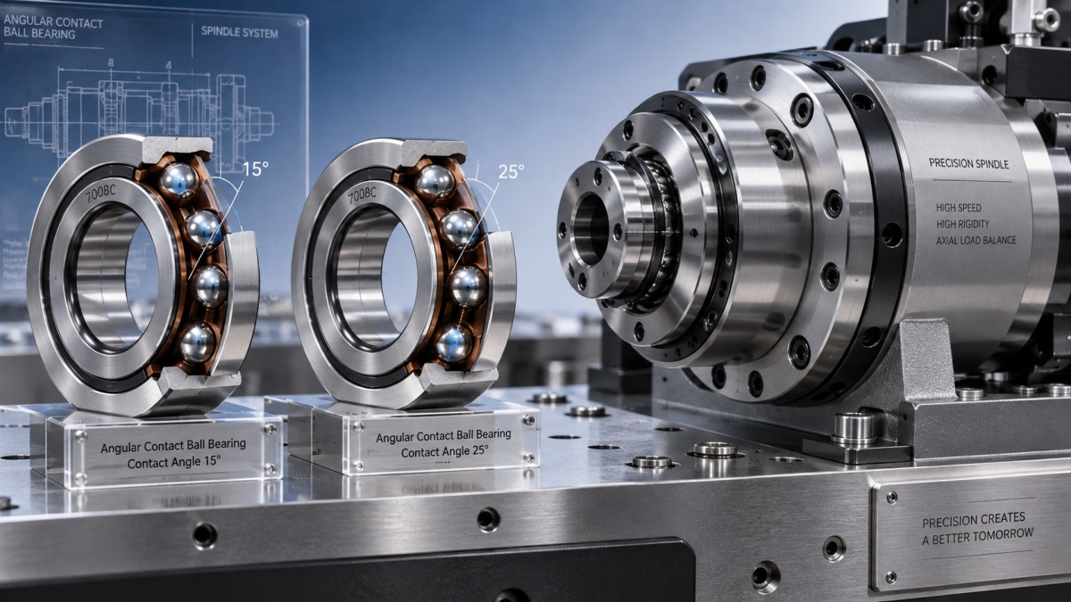
The contact angle is the angle between the line of force through the ball and raceway contacts and a plane perpendicular to the bearing axis. Increasing that angle gives the contact force a larger axial component. In a simplified geometric model, the axial component is proportional to the sine of the angle. This explains why a larger angle generally favors axial load support.
That relationship is useful for understanding direction, but it is not a bearing capacity calculation. Actual capacity depends on ball size and number, raceway geometry, material, and load distribution. Comparing two bearings solely by angle can be misleading when their internal designs differ.
Angles such as 15°, 25°, and 40° appear in angular contact bearing catalogs, although available choices depend on the series and manufacturer. Within comparable designs, a smaller angle commonly suits high-speed spindle duties, an intermediate angle offers a compromise for combined loading, and a larger angle favors heavier thrust and greater axial stiffness. These are selection tendencies, not universal application boundaries.
Nominal contact angle also differs from operating contact angle. Preload, external loading, fits, and thermal expansion alter contact conditions. At high speed, centrifugal forces acting on the balls can change the inner and outer raceway contact angles. A catalog angle therefore describes the design; it does not fully describe the bearing under every operating condition.
Why a smaller angle does not guarantee a faster bearing
A smaller angle generally supports favorable high-speed behavior within a comparable bearing family. However, a bearing’s usable speed is also constrained by friction, ball dynamics, cage behavior, lubricant delivery, and heat removal. Changing contact angle while overlooking these factors can produce little improvement—or introduce a load problem elsewhere.
Consider a spindle with moderate radial load, light thrust, and long periods at high speed. A smaller-angle design may provide sufficient axial support with favorable running characteristics. If cutting forces generate substantial thrust or demand tight axial positioning, that same selection may require greater preload or a different arrangement. Increasing preload to compensate for inadequate stiffness can consume part of the expected speed advantage.
Bearing size matters as well. The same rotational speed imposes different operating demands on small and large bearings. Catalog comparisons should account for bearing dimensions and internal construction rather than treating an rpm value as transferable between sizes.
Published reference speeds and limiting speeds also require careful reading. They may describe different thermal or mechanical constraints and rely on specified lubrication, mounting, and load conditions. A speed value for an individual bearing does not automatically apply to a preloaded pair. Use the manufacturer’s guidance for the actual arrangement and operating conditions, including any applicable speed reductions.
Lubrication can become the governing constraint before the nominal angle does. Excess grease can increase churning and temperature; insufficient lubricant delivery can compromise film formation. Oil-based systems introduce their own requirements for flow, viscosity, and heat removal. A credible speed assessment connects the bearing selection to the lubrication system rather than assuming that a high-speed designation resolves both.
Preload and arrangement can shift the compromise
Preload removes internal play and establishes stiffness before external loading begins. It can improve running accuracy and help maintain suitable contact conditions, but it also raises internal load and friction. Excessive preload can increase temperature and reduce fatigue life even when the external load appears modest.
The operating preload may differ substantially from the assembly preload. Shaft and housing temperatures, fits, component materials, and bearing spacing affect thermal growth. Depending on the arrangement, differential expansion can increase or decrease preload. A satisfactory cold rotation check therefore provides limited evidence about behavior after the machine reaches operating temperature.
Rigid position preload and spring preload respond differently to these changes. A rigid arrangement can provide high stiffness but requires close control of dimensional and thermal effects. A spring arrangement can accommodate movement and help maintain a more consistent preload force, with different stiffness characteristics. The appropriate choice depends on the machine’s accuracy requirement and thermal behavior.
Arrangement is equally important because a single-row angular contact bearing principally supports axial load in one direction. Applications with reversing thrust generally require an opposed arrangement or another bearing configuration capable of supporting both directions.
- Back-to-back pairs: Their diverging load lines provide greater resistance to overturning moments, making them useful where shaft tilting must be controlled.
- Face-to-face pairs: Their converging load lines provide lower moment rigidity than comparable back-to-back pairs, and their response to alignment and mounting conditions differs.
- Tandem arrangements: Bearings oriented in the same direction share axial load when correctly matched, but reverse thrust requires support from an opposing bearing or bearing set.
These differences can outweigh a modest change in contact angle. For an overhung tool or load, moment stiffness may govern selection. For sustained one-direction thrust, load sharing may dominate. Increasing the angle alone will not correct an unsuitable arrangement.
Reading a specification without assuming performance
A useful example is NTN-HTA030UAT2DB-Angular Contact Ball Bearing, listed under model HTA030UAT2DB/GNP4 with dimensions of 150 mm bore, 225 mm outside diameter, and 67.5 mm width. Those dimensions provide a starting point for checking the installation envelope. They do not establish the contact angle, permissible operating speed, or axial stiffness.
The listing includes P4 precision availability, but precision class and contact angle answer different questions. Precision concerns dimensional and running accuracy. It does not independently establish preload, load capacity, or thermal performance. Likewise, a general list of clearance classes cannot substitute for the preload specification of a matched angular contact bearing set.
For a specific order, the manufacturer’s designation information and technical drawing should establish the supplied configuration. Suffix meanings can vary across brands and bearing families. The evaluator needs the actual contact angle, matched arrangement, preload designation, load ratings, and lubrication conditions associated with the speed data. Dimensional compatibility and a precision label alone are insufficient grounds for approving a substitution.
Choosing an angle for the actual duty
Begin with the operating load spectrum: radial load, axial load in each direction, peak events, overturning moment, and the time spent at each speed. Separate continuous conditions from short transients. A peak thrust event may govern static safety, while sustained combined loading and operating temperature govern fatigue life and thermal suitability.
Then identify what limits acceptable machine behavior. For a high-speed spindle with light thrust, begin by evaluating smaller-angle designs. For a thrust-heavy application with demanding axial positioning, examine larger-angle designs. Where both requirements are substantial, compare complete bearing sets rather than expecting an intermediate angle to resolve every constraint.
The final comparison should cover three connected checks: load capacity and calculated life under the duty cycle; stiffness under working loads; and thermal suitability at the intended speed with the selected preload and lubrication. Use the load factors and calculation methods applicable to the specific bearing. Equal external loads can produce different internal conditions when angle, preload, or arrangement changes.
During commissioning, temperature trends, axial displacement, and running behavior can help assess whether the assembled system behaves as expected. Rising temperature alone does not identify the wrong contact angle; excessive preload, lubricant quantity, fit, or inadequate heat removal may produce similar symptoms. If a candidate meets thrust requirements only with heavy preload, or meets speed requirements only under lubrication conditions the machine cannot provide, the bearing arrangement deserves another look before the specification is released.
Navigation
Send Us A Message
consult

Jinan Lanyu Import & Export Co., Ltd. is a bearing manufacturing enterprise specializing in the import and export trade of bearings. Covering a total area of 50,000 square meters, the company boasts an annual production capacity exceeding 20 million sets and is dedicated to the manufacture of high-quality bearings.

First class quality service and professional after-sales team.
Get in Touch
*We respect your confidentiality and all information are protected.
