


A HIWIN Linear slider should use the lowest preload that satisfies the required stiffness and load-reversal stability under actual operating conditions. Increasing preload reduces internal clearance and raises contact stiffness, but it also increases running resistance and sensitivity to installation error. A higher preload class therefore needs justification through load, deflection, and drive calculations; it does not automatically improve positioning accuracy.
The first specification decision is the guide series. Preload codes, available classes, and their relationship to the basic dynamic load rating belong to the selected series and catalog revision. A code copied from another guide family is insufficient to define the required preload.
Reading preload classes without confusing them with accuracy grades
Preload creates an internal contact load between the rolling elements and raceways before an external working load is applied. In a recirculating ball guide, this is commonly established through controlled ball sizing. The resulting elastic deformation removes clearance and changes the guide’s load–deflection behavior.
For HIWIN HG-series ball guides, familiar designations include Z0 for very light preload, ZA for medium preload, and ZB for heavy preload. Other families have different options or definitions. Use the applicable series table to establish the specified preload range and reference load rating rather than treating these codes as a universal scale.
Accuracy grade and preload class describe different properties. Accuracy grades address specified geometric tolerances, such as running parallelism and dimensional variation. Preload governs the contact condition and stiffness. A heavily preloaded carriage on a geometrically inaccurate installation will still follow that installation’s errors.
Where additional preload improves accuracy
Preload is valuable when a changing force causes measurable displacement at the working point. During cutting, pressing, or acceleration, the carriage experiences forces and moments that elastically deform its contacts. Increasing preload raises stiffness in the relevant operating range, reducing the displacement produced by a given load change.
A useful first estimate is displacement ≈ force change / effective stiffness. Effective stiffness must include the guide contacts, rail attachment, carriage mounting plate, machine base, and other compliant parts. If the mounting plate bends substantially, increasing carriage preload produces only a limited improvement at the tool or workpiece.
Moments deserve separate attention. An offset load creates unequal reactions between carriages, even when total payload is moderate. Rail spacing, carriage spacing, and the distance from the guide plane to the working point can influence deflection more strongly than changing the preload class. Evaluate individual carriage loads instead of dividing the total force equally by the number of blocks.
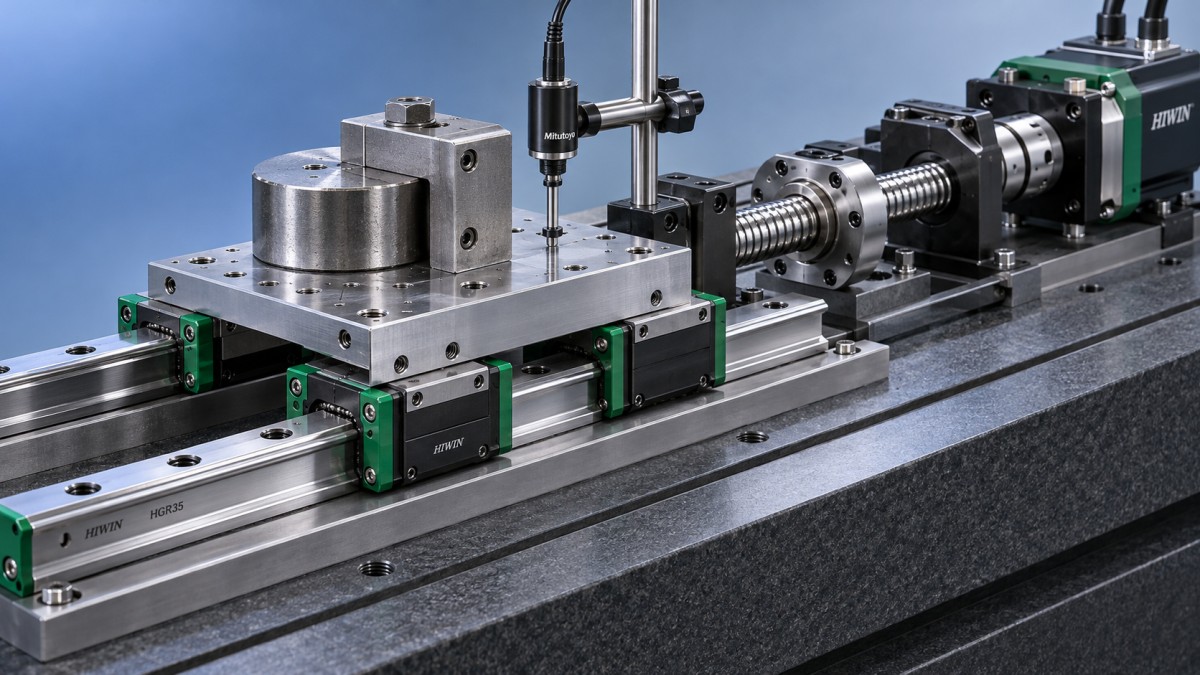
Preload also changes behavior during load reversal. As external load increases, the contact loads redistribute; opposing contacts can eventually unload. Stiffness then changes, so one constant stiffness value cannot describe every load condition. Catalog load–deflection curves are more useful than a general statement that a particular class is “rigid.”
Encoder position alone does not reveal all these effects. A motor encoder measures motion upstream of screw deformation and structural compliance. Even a linear scale measures displacement at its own location, which can differ from movement at an offset working point. Compare preload options using the location where accuracy actually matters.
Friction, drive force, and thermal drift
Higher preload increases internal contact forces and generally raises the rolling-contact contribution to resistance. Total carriage resistance also includes seals, lubricant displacement, and recirculation effects. At light loads, seal drag can represent a substantial share of measured force, making preload differences less obvious than expected.
Breakaway force and steady running force should be measured separately. A carriage that moves smoothly at production speed can still show poor behavior during slow approach or repeated reversals. Grease condition, seal contact, and installation stress can affect these measurements, so a high starting force does not establish excessive preload by itself.
For drive sizing, include guide resistance alongside process force, acceleration force, transmission losses, and other mechanical loads. On a screw-driven axis, convert the required thrust to motor torque using the screw lead and transmission efficiency. Retain adequate margin for acceleration and temperature-dependent changes instead of sizing from unloaded running resistance alone.
Frictional heating increases with resistance and travel speed; the mechanical power dissipated is approximately force multiplied by velocity. Temperature rise then depends on duty cycle and heat removal. Uneven heating can distort the support structure or shift the working point, offsetting the reduction in elastic deflection achieved through extra preload.
Mounting errors can imitate excessive preload
Rail parallelism, mounting-surface flatness, and the relative height of paired rails affect the installed contact load. A rigid carriage assembly forced across misaligned rails develops additional internal loading beyond its specified preload. The result can include elevated drive current, localized resistance, and early raceway damage.
Increasing preload reduces the assembly’s tolerance for these errors. A heavily preloaded guide requires mounting surfaces and alignment appropriate to its series, size, and accuracy grade. Bolt tightening cannot reliably pull a distorted rail seat into a correct geometry; it can transfer that distortion into the rail.
Follow the specified reference surfaces and tightening sequence. Where the machine design permits, measure carriage resistance along the travel before attaching components that introduce additional constraint. Repeat the measurement after installing the second rail, connecting the carriage plate, and coupling the drive. A marked increase after one assembly stage helps locate the source of unwanted loading.
Resistance concentrated at particular travel positions points toward local alignment error, contamination, rail damage, or attachment distortion. Uniformly elevated resistance suggests a different investigation, including seals, lubricant, or preload selection. These patterns guide diagnosis but require confirmation through inspection and measurement.
Preload is not a substitute for load capacity or lubrication
Preload consumes part of the contact system’s loading allowance. It does not increase the published basic dynamic or static load rating. Fatigue-life assessment must follow the selected guide’s method for incorporating preload, external loading, moments, and operating factors. Greater stiffness alone is insufficient evidence of longer service life.
Lubrication must match speed, temperature, stroke, and duty cycle. Excess grease can raise resistance during initial running, while inadequate lubrication increases damaging contact interaction. Short strokes need particular attention because lubricant distribution and rolling-element circulation differ from those in long-travel operation.
Rotary bearing specifications use a different classification system. For example, the SKF 6313-Z Deep Groove Ball Bearing is listed with dimensions of 65 mm bore, 140 mm outside diameter, and 33 mm width. Its radial-clearance options describe a rotary bearing condition; they cannot be translated into HIWIN guide preload codes. Both components involve elastic rolling contact, but their specification terms are not interchangeable.
Comparing preload options on the assembled axis
Begin with the working-point deflection allowance and the worst relevant combination of forces and moments. Separate geometric travel error from load-induced movement. Then compare candidate preload classes using the selected series’ stiffness information and mounting tolerances.
Validation should reproduce the conditions that distinguish the options: slow reversals for positioning stability, representative process loads for deflection, and sustained travel for thermal behavior. Record running force or drive current against position, together with working-point displacement and temperature. Keep lubrication, seals, speed, and assembly conditions consistent between comparisons.
A heavier class earns its place when the measured reduction in load-induced displacement is necessary and the assembled axis retains acceptable resistance and thermal stability. If preload changes barely affect working-point displacement, investigate structural compliance, guide spacing, or the measurement arrangement before increasing it again.
Navigation
Send Us A Message
consult

Jinan Lanyu Import & Export Co., Ltd. is a bearing manufacturing enterprise specializing in the import and export trade of bearings. Covering a total area of 50,000 square meters, the company boasts an annual production capacity exceeding 20 million sets and is dedicated to the manufacture of high-quality bearings.

First class quality service and professional after-sales team.
Get in Touch
*We respect your confidentiality and all information are protected.
