


An SKF FNL513A housing retrofit can proceed as a direct replacement only when the mounting interface, shaft position, bearing arrangement, and installed envelope agree with the existing machine. Matching the housing designation or the visible bolt pattern alone does not establish compatibility. A replacement may bolt into place yet shift the shaft axially, interfere with a coupling, or prevent the bearing arrangement from accommodating thermal expansion.
Before purchasing an SKF FNL513A cast flanged housing, compare a manufacturer drawing for the exact supplied designation with measurements taken from the installation. The checks below identify the dimensions that belong in that comparison. Numerical acceptance limits should come from the machine requirements and the applicable component drawings; a generic housing size cannot establish them.
Establish the mounting face and shaft axis first
For a flanged housing, start with the machine surface against which the flange seats. Use that surface as the axial datum, then establish the intended shaft centerline relative to fixed machine features. A “shaft center height” measured from the floor or a nearby guard can be misleading if those features do not locate the housing.
Record the shaft center position in both directions across the mounting face. Where the machine uses a locating recess, register, or pilot, measure its diameter and depth and identify which feature controls alignment. Bolts may provide clamping while a separate register establishes position. Treating bolt clearance as an alignment adjustment can conceal a mismatch in the locating interface.
The comparison should cover:
- Mounting-hole positions: hole count, center-to-center distances, and the orientation of the pattern relative to the shaft axis.
- Hole details: clearance or threaded holes, diameters, and any counterbores or recesses that affect fastener seating.
- Locating features: the dimensions and engagement depth of any register or pilot shown on the housing and machine drawings.
- Flange geometry: outside dimensions, contact area, and thickness at the fastening points.
- Machine opening: sufficient clearance for any housing portion, seal assembly, or shaft feature extending through the support.
Use measured hole centers rather than outside-edge estimates. Paint, corrosion, damaged hole edges, and previous modifications can distort a quick tape measurement. If the installed housing obscures a locating feature, allow for inspection during disassembly before releasing a purchase that depends on that feature.
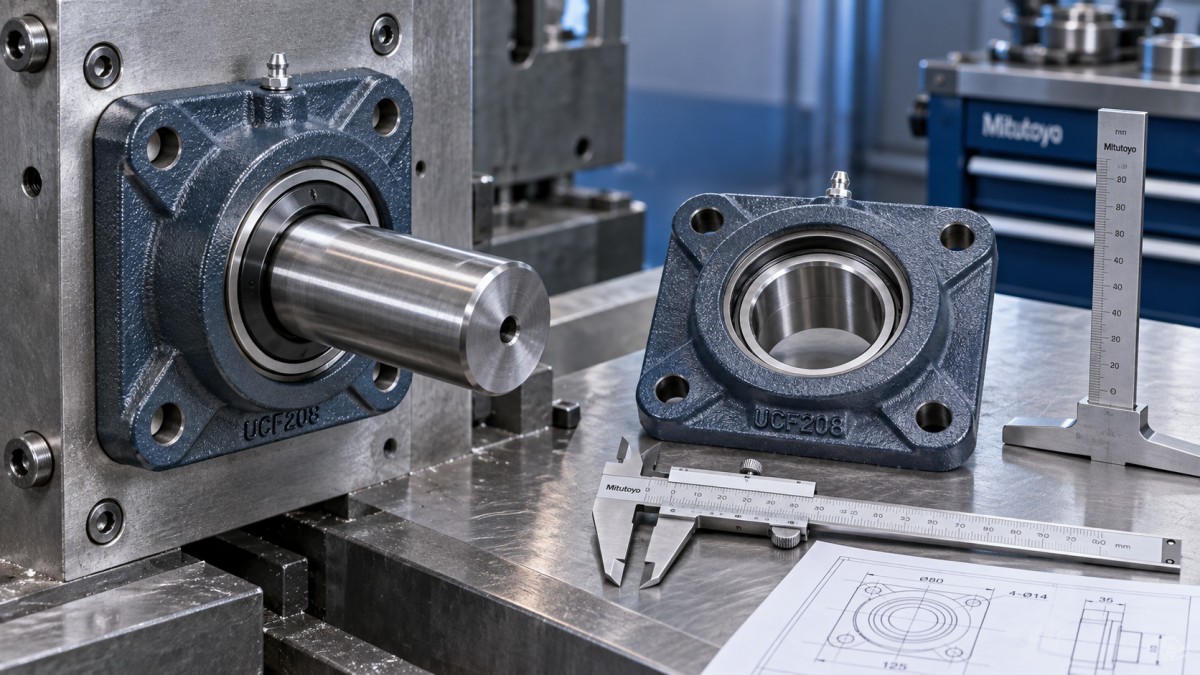
Matching the pattern still leaves the support condition unresolved. Check that the mounting face is flat and provides the intended contact area. A cracked bracket, distorted plate, or uneven stack of old shims can compromise alignment even when the replacement dimensions agree. Any adapter plate should be assessed for stiffness, fastening, and alignment as part of the retrofit.
Check the axial dimensions that determine where the shaft runs
Flange thickness affects more than bolt length. Together with the bearing position inside the housing, it determines the axial relationship between the machine mounting face and the supported shaft. Compare the distance from that face to the bearing reference position defined on the drawing, rather than comparing only the overall housing depth.
Then follow the dimensional chain along the shaft. Include shaft shoulders, sleeves where applicable, locking components, bearing width, spacers, seals, and the neighboring coupling or driven element. Establish which components locate the shaft and which merely retain or seal the assembly. This prevents a replacement housing from being accepted on external dimensions while changing the internal stack.
Fasteners need a separate check. A thicker flange or added adapter can reduce thread engagement; a thinner flange can allow an existing bolt to bottom in a blind hole before clamping the housing. Confirm the available engagement, washer arrangement, head clearance, and tightening access against the fastening design.
For an assembly connected to a coupling, compare the resulting shaft-end position with the coupling’s permissible axial setting. Also check pulley, sprocket, or gear alignment where relevant. An axial discrepancy can create work outside the housing replacement itself, so include those adjustments in the installation scope before the shutdown is scheduled.
Verify the bearing arrangement inside the housing
The housing designation alone is insufficient to select the bearing, shaft fit, or mounting accessories. Confirm the bearing designation and mounting arrangement intended for the exact housing version, including any sleeves, locating components, seals, and end covers. Obtain an assembly drawing or a documented component list that connects these parts to the housing being supplied.
Begin with the shaft diameter at the bearing mounting position, but distinguish that measurement from the bearing bore. Where a sleeve is used, the bearing bore and shaft seat have different dimensions. A procurement instruction that gives only the shaft diameter can therefore leave an essential part of the assembly undefined.
The housing seat also requires more than a diameter comparison. Check its width, the permitted bearing dimensions, and the space occupied by locating components. Bearings with superficially similar outside dimensions can have different mounting requirements or load behavior. Substitution requires a bearing selection review as well as a dimensional check.
Identify whether this support locates the shaft axially or allows axial movement. In a shaft supported at more than one position, thermal growth must be accommodated by the intended arrangement. An unintended locating component can restrict that movement; omitting a required component can leave the shaft position uncontrolled. Document the function of each support before ordering internal parts.
Seals belong in the same dimensional review. Verify the shaft diameter where each seal operates, the required running surface, and the axial space occupied by the seal arrangement. A worn seal track or a change in seal position may require shaft repair or a different approved arrangement, even when the bearing seat remains serviceable.
Finally, check installation access. The correct parts can still be difficult to assemble if a shaft shoulder, coupling, or adjacent structure prevents fitting a sleeve, tightening a locking component, or installing a cover. Establish the assembly sequence while the drawing and site measurements are being compared.
Measure the service envelope, then release a defined assembly
Overall housing dimensions describe only part of the space required. Measure clearance to the frame, guards, coupling, pipework, and neighboring equipment. Include protruding fasteners, lubrication fittings, covers, and any parts that must be removed during servicing.
Leave space for the maintenance operation itself. A grease connection needs access for the intended equipment; a cover needs a removal path; locking components need tool clearance. Where a guard must change, include that work in the retrofit package so the installation team does not discover it after the housing is fitted.
A useful release document is a marked drawing supported by a short comparison sheet. For each critical feature, record the required dimension, the site measurement, the proposed housing dimension, and the engineering acceptance limit. Separate dimensions taken from drawings from those measured on the machine, and record the datum used. Photographs help explain access constraints but cannot replace measurements of concealed interfaces.
Release the purchase when the comparison establishes a workable mounting interface, the intended shaft position, a complete bearing arrangement, and adequate operating and maintenance clearance. Where an adapter, shaft modification, or revised seal arrangement is necessary, attach the approved modification drawing and include the additional parts in the order scope.
The installation handover should identify the alignment checks to perform before startup and the parts that establish axial location. With those decisions settled, the project team can schedule the retrofit around a defined assembly and a known sequence of work, with fewer dimensional decisions left to the shutdown crew.
Navigation
Send Us A Message
consult

Jinan Lanyu Import & Export Co., Ltd. is a bearing manufacturing enterprise specializing in the import and export trade of bearings. Covering a total area of 50,000 square meters, the company boasts an annual production capacity exceeding 20 million sets and is dedicated to the manufacture of high-quality bearings.

First class quality service and professional after-sales team.
Get in Touch
*We respect your confidentiality and all information are protected.
